IBH Link UA:SINUMERIC
Contents
Features
- Address space compatible with OPC 40502 - UA for Computerized Numerical Control (CNC) Systems
- Ethernet access to all models of the 840D-SL (Solution Line) via Ethernet
- Ethernet access to all models of the 840D Power Line via MPI or PROFIBUS with the IBH Link S7++
- Number of connectable CNC controls limited only by memory usage
- Access to the complete data of the NCK and the PLC on all models
- Automatic detection of the SINUMERIK model
- Automatic detection and assignment of the NC machine configuration (number of channels, axes, spindles and their assignments)
- Automatic readout of the machine data, R-parameters and the global as well as channel-specific GUDs with their configured names.
- Selection of the most important NC data already preconfigured
- Address space can be extended as required via NC-VAR-Selector
- Import of the PLC project via the free available IBH OPC UA Editor
- Configuration exportable as XML for editing or extension
- XML configuration can be uploaded via web browser
Configuration
The IBH Link UA can be used to read data from SINUMERIK controllers of the PowerLine and SolutionLine series. In the SolutionLine series, which already has Ethernet ports, the IBH Link UA can be connected to the interfaces X120 and X130.
According to the Siemens documentation, port 102 is always enabled for S7 communication in the firewall of the SINUMERIK so that no changes are required here. If necessary, this can be adjusted on the CompactFlash of the SINUMERIK in the file /card/system/usr/etc/basesys.ini (value FirewallOpenPorts) (which may be present several times according to the documentation). By default port X120 is set to 192.168.214.1, port X127 to 192.168.215.1 and port X130 to DHCP. If the IBH Link UA is connected to port X130, you have to make sure that port X130 can either get an address from a DHCP server or gets a fixed IP address. Further information can be found here: https://support.industry.siemens.com/cs/document/59715134/sinumerik-840d-sl%3A-routing-from-x120-to-x130-for-pg-pc-firewall-configuration?dti=0&lc=en-SE
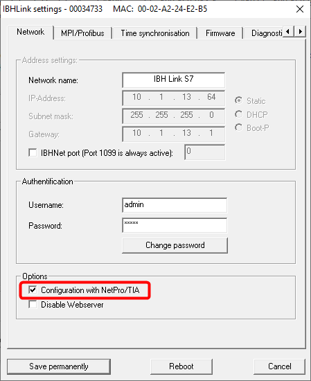
For the PowerLine models, which do not have an Ethernet interface, the IBH Link S7++ is additionally required. Furthermore it has to be considered that the PowerLine does not allow any number of connections. These are normally 5 connections to the NCK and 2 connections to the PLC, whereby the always connected HMI already occupies one of the connections. To establish a connection, the IBH Link S7++ must be switched to the configured mode:
PowerLine
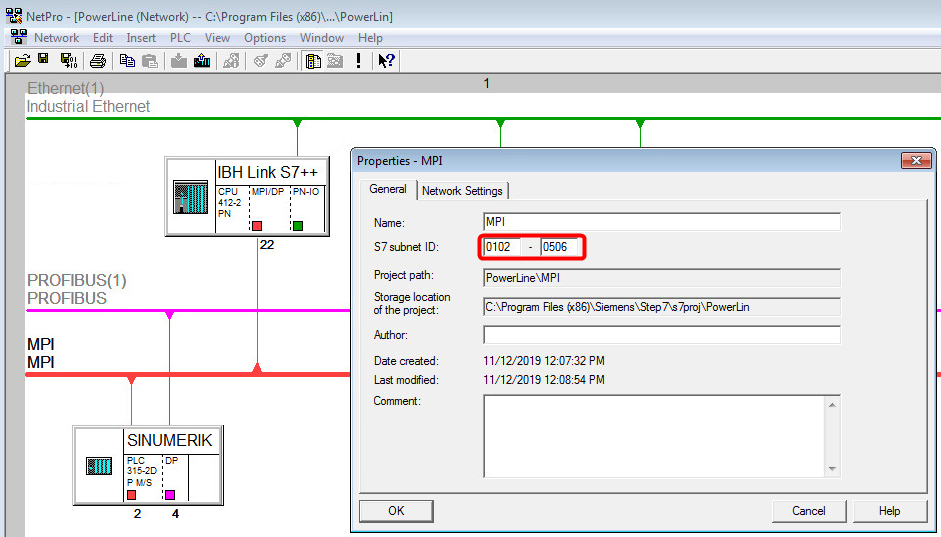
In Netpro the IBH Link S7++ is inserted as dummy CPU at STEP 7 and connected to the MPI/DP network. In TIA the same procedure has to be done in the view Devices and Networks: :
If the SINUMERIK is not yet networked, the default values 0102-0506 should be set for the Subnet ID. If it is already networked, the IBH Link S7++ is simply inserted into the existing project. In this case the Subnet ID may not be changed, but must be specified when creating the station. This configuration is loaded into the IBH Link S7++.
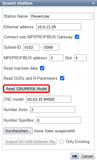
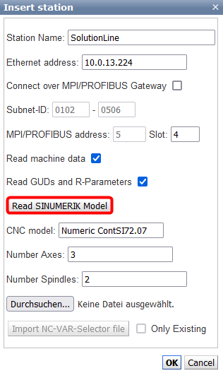
In the web interface, a new station can now be inserted with the button Insert Sinumeric:
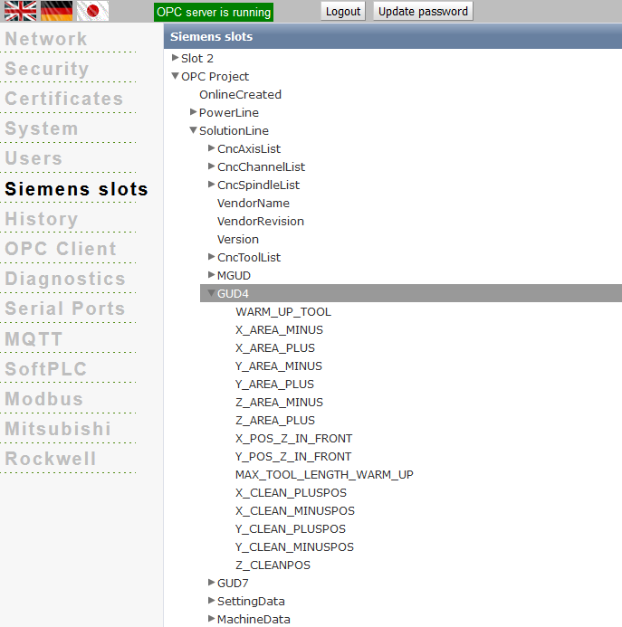
The Sinumerk model can now be read out automatically. Afterwards the data read out from the SINUMERIK appears under OPC Slots. The data model corresponds to the current model of the OPC Foundation:
https://github.com/OPCFoundation/UA-Nodeset im Zweig CNC
The SINUMERIK data is mapped into this model in the best possible way in order to use the tags with an OPC UA client: :
SolutionLine
With the SolutionLine, the configuration of the IBH Link S7++ is not necessary, since these have an Ethernet interface:
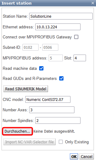
In addition, further tags can also be selected with the NC-Var selector from Siemens and read in as IL file. When reading in, the information is automatically assigned to the channels and axes, if possible. Otherwise the values (also structured) appear in the root:
Extend NC Var selector with machine data
On the HMI connected to the NCU, the file Ncv*.mdb (ncvartrace.mdb or ncv_NcData.mdb) is located in the folder C:\Siemens\Sinumerik\HMI-Advanced\mmc2. To find them, you can search for *.mdb and ignore the files found in non-Siemens folders. The Ncv*.mdb files can then be opened from NC-Var selector 10.00.03.00 via Project - Open Database. Alternatively, the database can be connected with the tool MDB Admin https://sourceforge.net/projects/mdbadmin/ (Database - Connect). Afterwards it can be exported into the Excel format (Database - Tools - Export as XLS). With this information you can manually create a NC-VAR selector .awl.
Reading R-Parameters
This PDF can be found at https://support.industry.siemens.com/tf//WW/en/posts/reading-r-parameters-from-nck/50938?page=0&pageSize=10: file:Read_R_parameters.pdf
This describes the reading of the channel-specific R parameters for the GET block integrated in the PLC. This also works with the IBH Link UA (page 1-5, from page 6 the integrated PLC is described). With the NC VAR selector you must select Area C[.] Component RP Variable rpa[.].
