IBHNet:Technical Data IBH Link S7
The IBH Link is an ethernet gateway. IBH Link fits in a DSub-housing. It consists of a complete fieldbus master together with a 10/100 MBit/s ethernet interface which uses Auto-Negotiation to determine the speed of the network ist is connected to.
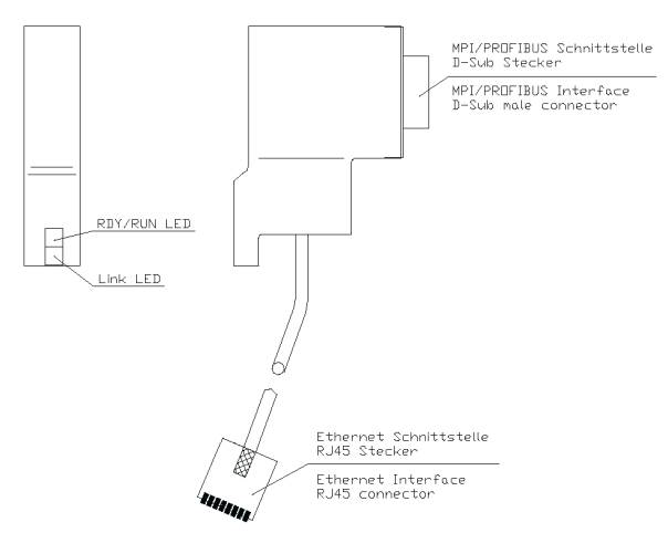
Due to the design in a D-Sub housing the IBH Link can be directly attached on the fieldbus-connector of a MPI-capable device. The IBH Link is connected to the next hub or switch by a 3m long STP-cable.
If the IBH Link S7, IBH Link S5++ or the IBH Link S7 Plus need to be connected directly to the PC, a crossed cable (Cross Over) may be required with older network cards. An IBH CX, IBH Link S7++ and the IBH Link S7++ HS can always be used with a normal or a crossed cable.
The IBH Link is directly supplied over its MPI interface.
The configuration takes place over ethernet. Therefore you have to start IBHNet on a PC which is connected to the same ethernet segment like the IBH Link.
A diagnosis channel to the IBH Link is established over a defined TCP/IP port. The configuration is stored in a flash memory inside the IBH Link.
Contents
Drawing :
MPI-Interface
| pin | signal | explanation |
|---|---|---|
| 1 | - | unused |
| 2 | DGND | reference potential |
| 3 | RxD/TxD-P | receive- / send-data-P |
| 4 | - | unused |
| 5 | DGND | reference potential |
| 6 | - | unused |
| 7 | VP | supply voltage 24 V |
| 8 | RxD/TxD-N | receive- / send-data-N |
| 9 | - | unused |
For the connection of the IBH Link to the MPI interface of a Siemens S7 or another MPI-capable device no connection-cable is needed. The IBH Link is directly attached on the MPI interface of the device.
No external power supply is required, the IBH Link is supplied by the MPI interface.
ATTENTION:
- Due to its compact size, the IBH Link does not have a reverse voltage protection!
- Some PLCs may have a temporary error condition on the the MPI/Profibus for the startup period of the internal profibus chip, if the IBH Link is connected in an angular position. If the IBH Link needs to be connected to a PLC that reacts sensitive to this behaviour, the IBH Link must only be connected in powerless state of the PLC.
RJ45 connector
| pin | signal | explanation |
|---|---|---|
| 1 | TX+ | send-data |
| 2 | TX- | send-data |
| 3 | RX+ | receive-data |
| 4 | - | unused |
| 5 | - | unused |
| 6 | RX- | receive-data |
| 7 | - | unused |
| 8 | - | unused |
Connection with Hub/Switch
RJ45 connector
| IBH Link | Hub / Switch | PC |
LED Controls
| RDY / RUN red | Flashing (1 Hz) | Bootloader active |
| Flashing fast (10 Hz) | Booting, Firmware gets initialized | |
| RDY / RUN green | On | Ready, IP-Address set |
| Flashing irregular | no IP-Address or Address exists in the network | |
| Flashing fast (10 Hz) | Firmware-Update in Progress | |
| Link LED | On | Connection to the ethernet is up |
| Off | No connection to the ethernet |
Technical Data
| Ethernet-Interface | |
| speed | 10 / 100 MBit/s |
| interface | 10 / 100 Base-TX |
| Connector RJ45 | |
| PROFIBUS-Interface | RS485, max 12 MBaud |
| PROFIBUS-Interface | according to EN 50170 |
| supply voltage | +24 V / 50 mA |
| operating temperature | 0 °C - 50 °C |
| IP 20 | |
| dimensions | 65 x 48 x 16 mm |
| weight | ~ 140 g with cable |

