IBH OPC UA:Configuration with STEP7
Configuration of the IBH OPC UA Server/Client with STEP7
Contents
Description
In the following example the configuration with STEP7 is shown.
The S7 IM151-8 station is connected with the IBH OPC UA Server/Client via Ethernet.
The following addresses were chosen in the example:
IP addresses:
| Station | Address |
|---|---|
| IBH OPC UA Server/Client | 192.168.10.125 |
| S7-1500 | 192.168.10.129 |
Configuration:
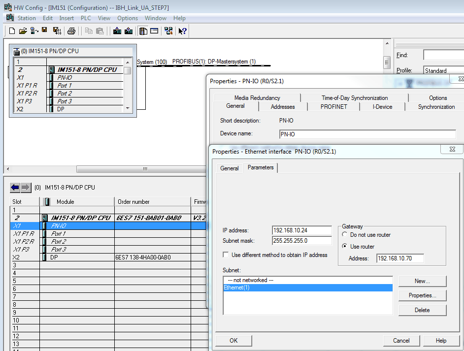
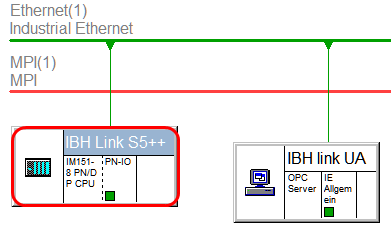
A new device will be added (in the sample a S7 IM151-8) and networked with Ethernet(1):
Now a DB can be created:
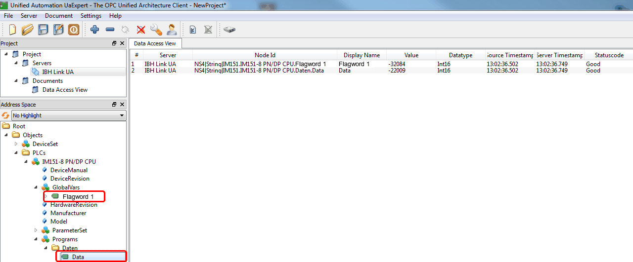
In our sample the symbols Data and Flagword 1 are defined within the symbolic table:
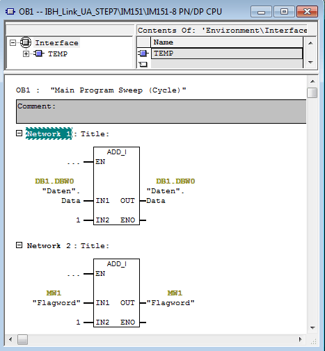
Within OB1 the data word 1 and flag word 1 will be counted in our example:
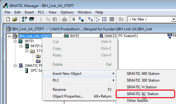
After downloading the blocks OB1 and DB1 to the IM151-8 a Simatic PC Station must be added:
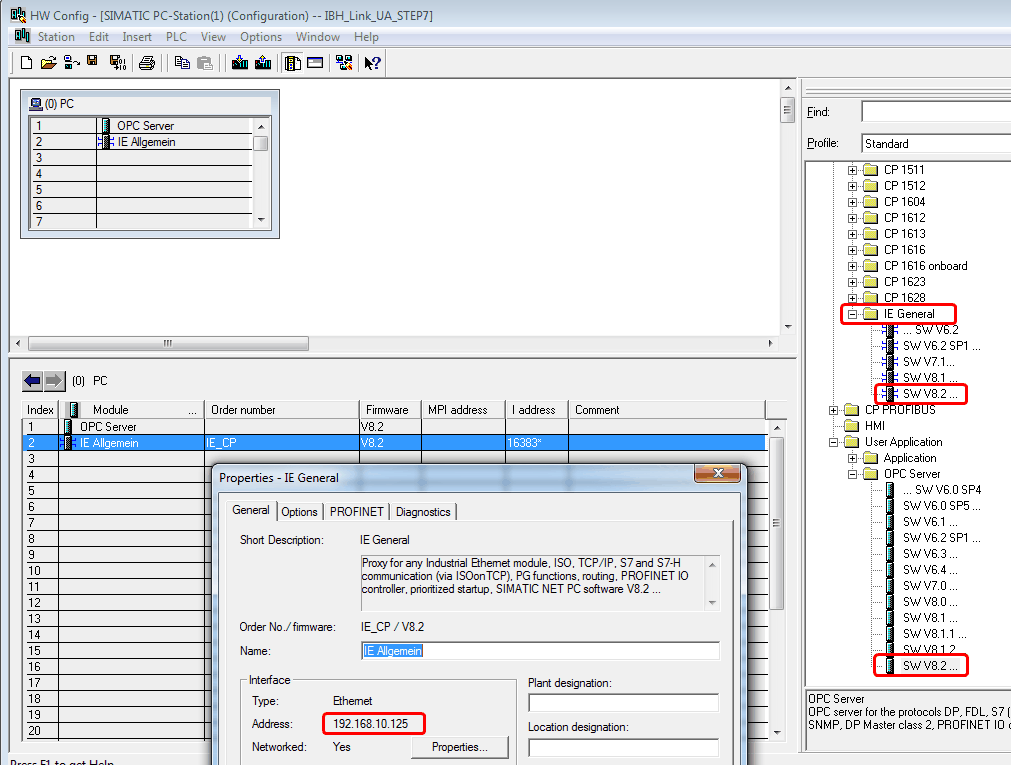
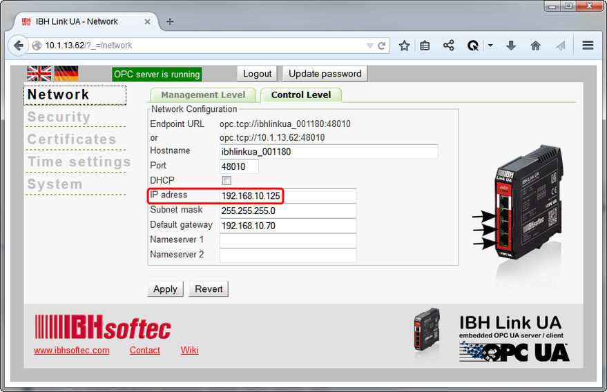
Within the properties of the Ethernet Port of the PC Station, the IP address of the IBH OPC UA Server/Client must be entered
after adding an OPC Server in slot 1 and an IE-module in slot 2
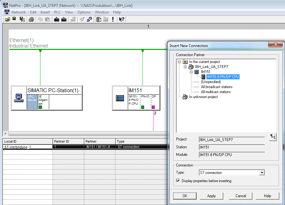
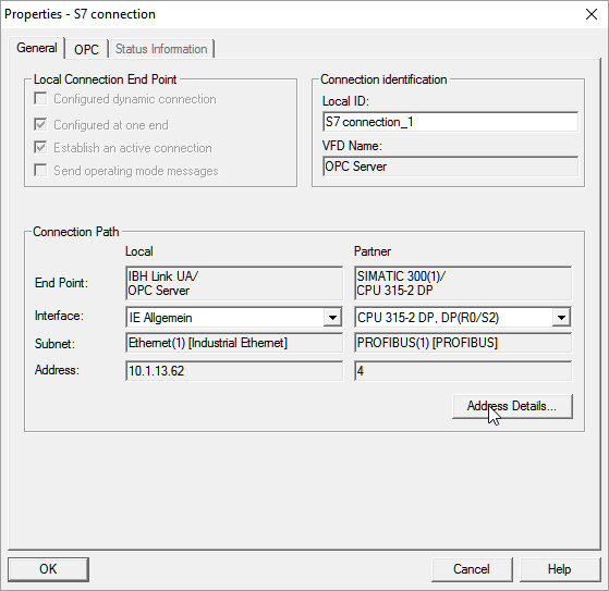
Now a S7 connection between the OPC Server and the PC station must be established:
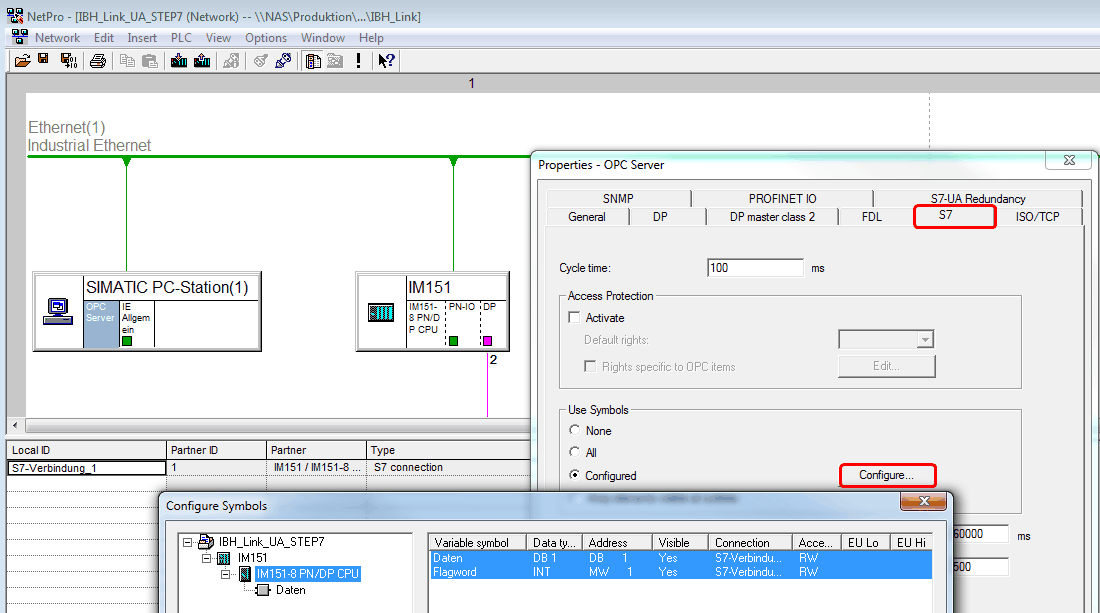
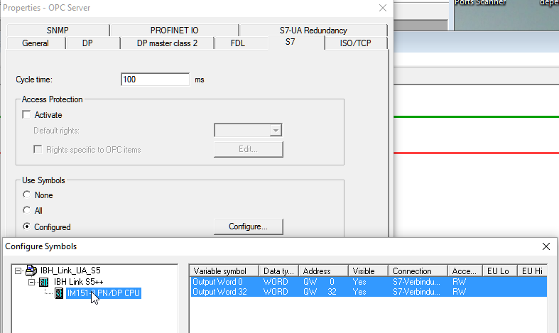
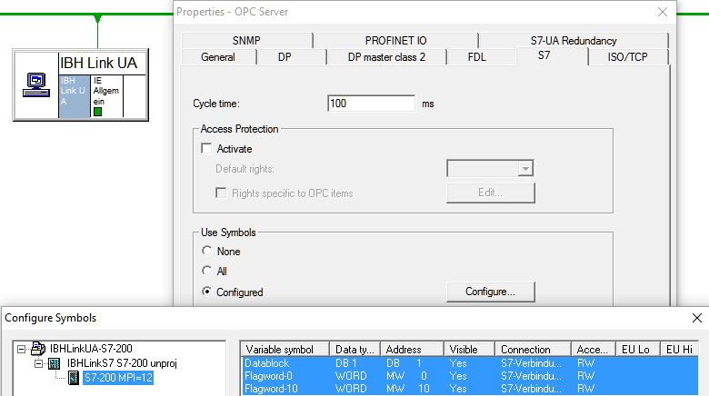
Within the properies of the OPC Server at <General> <S7> <OPC tags > the OPC Tags can be selected:
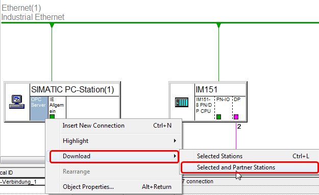
Now the configuration needs to be downloaded to the PLC and the IBH OPC UA Server/Client:
The configuration is now completed and the tags from the IBH OPC UA Server/Client are available.
STEP7 Sample: IBH Link UA with SIMATIC S5 via IBH Link S5++
Download: STEP7 Sample: IBH Link UA S5
SIMATIC® S5 PLC can be connected to the IBH Link UA via the IBH Link S5++
The IBH Link S5++ will be configured as a S7-300 station within NetPro::
The following station can be selected:
MLFB: 6ES7 412-2EK06-0AB0 V6.0
Rack 0, Slot 2
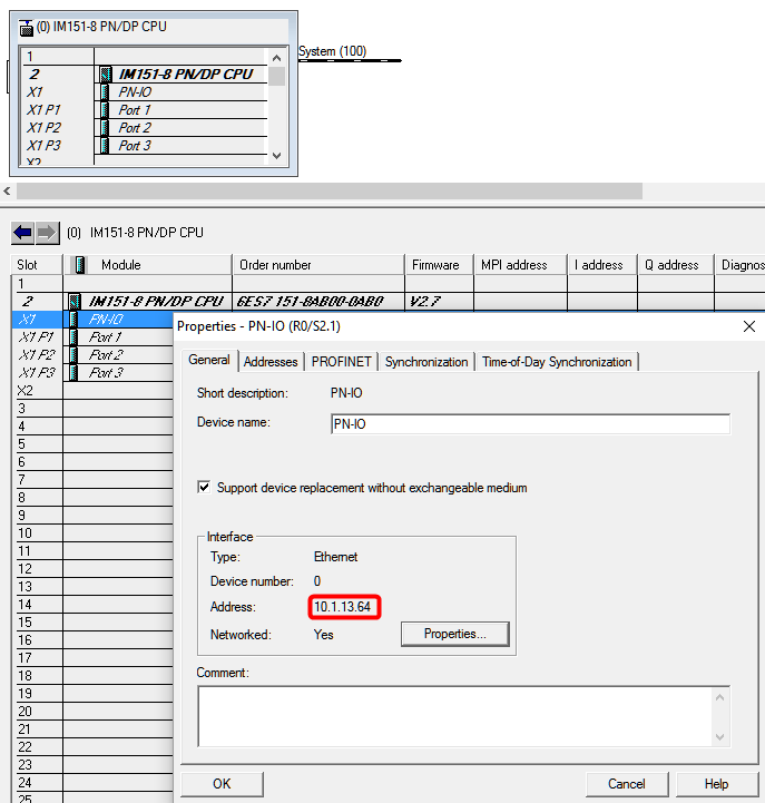
IP Address of the IBHLink S5++
Configuration of the Station within the hardware configurator:
The further pocedure can be found at Configuration with STEP®7]
STEP7 Sample: IBH Link UA with S7 315-2DP routet via IBH Link S7++
Download: STEP7 Sample: IBH Link UA with S7 315-2DP
S7-300 and S7-400 controllers which do not have an Ethernet port available can be connected via the IBH Link S7++ or the IBH Link S7++ HS to the IBH Link UA.
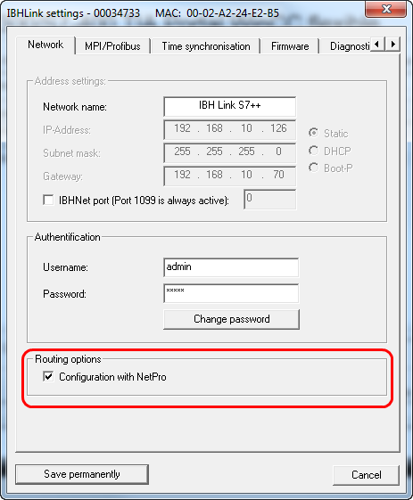
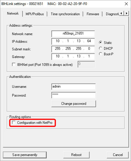
Within the IBHNet settings the routing mode must be activated. This mode is available beginning with firmware version 2.142.
With projected connections via RFC1006 it is not possible to communicate over unprojected connections any more!
The normal IBHNet communication over port 1099 via the IBHNet driver is not influenced from this setting.
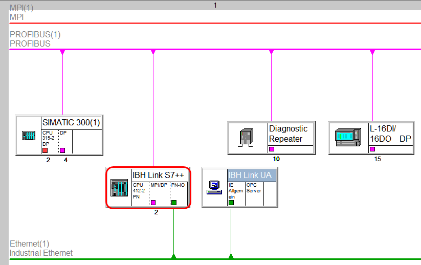
The IBH Link S7++ will be configured as a S7-400 station within NetPro and connected with the bus system (MPI or PROFIBUS)
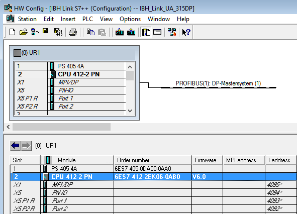
The following station must be selected:
MLFB: 6ES7 412-2EK06-0AB0 V6.0
Rack 0, Slot 2
MPI/PROFIBUS address of the IBHLink S7++
IP Address of the IBHLink S7++
Configuration of the Station within the hardware configurator:
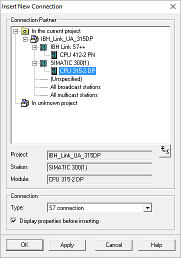
A routed S7 connection from the OPC Server to the S7 PLC must be set up::
The further pocedure can be found at Configuration with_STEP®7]
STEP7 Sample: IBH Link UA with S7-200 via IBH Link S7++
Notes about the configuration can be found within the ReadMe.txt.
Download: STEP7 Sample: IBH Link UA with S7-200 via IBH Link S7++
S7-200 controlers can be connected via the IBH Link S7++ or the IBH Link S7++ HS to the IBH Link UA.
Within the IBHNet settings the routing mode must be deactivated. This mode is available beginning with firmware version 2.142.
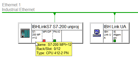
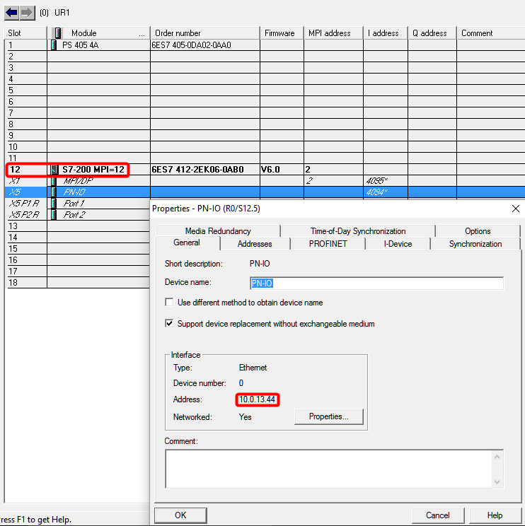
The IBH Link S7++ will be configured as a S7-400 station within NetPro wthin an UR1 Rack(18 slots)
MPI addresses of 2-18 for the S7-200 PLC are possible.
The slot of the CPU represents the MPI address.
The following station must be selected:
MLFB: 6ES7 412-2EK06-0AB0 V6.0
IP Address of the IBHLink S7++
Configuration of the Station within the hardware configurator:
For the PLC a symbol table and the DB1 has to be created, the OB1 should be deleted.
The further pocedure can be found at Configuration with_STEP®7]
STEP7 Beispiel: IBH OPC UA Server/Client with IBH SoftSPS
Download: STEP7 Sample: IBH OPC UA Server/Client with IBH SoftSPS
