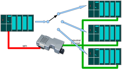
IBHLink S7++:PLC-PLC communication
Contents
- 1 Ethernet to MPI / PROFIBUS
- 2 Ethernet to PROFIBUS via PROFIBUS CP (Multiplexing)
- 3 MPI – Ethernet – MPI without projected configuration / MPI – Ethernet/MPI – IBH Link S5++
- 4 MPI – Ethernet – MPI with S7 conection (projected) / MPI – Ethernet / MPI – IBH Link S5++
- 5 Connection via IBH Link in routing mode
Ethernet to MPI / PROFIBUS
Requirements:
- SIMATIC Manager
- IBH Link S7++ / HS with Firmware >= 2.142
- CPU with MPI or PROFIBUS Interface
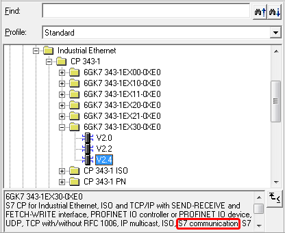
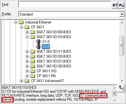
- CPU with Ethernet onboard or Ethernet CP. The Interface must support S7 connections. It can be checked within the hardware
properties: S7 connection active (Server means passive).
Download: STEP®7 Sample: Ethernet to MPI/PROFIBUS
Within NetPro the CPU must be connected with the Ethernet. An unspecified connection needs to be created:
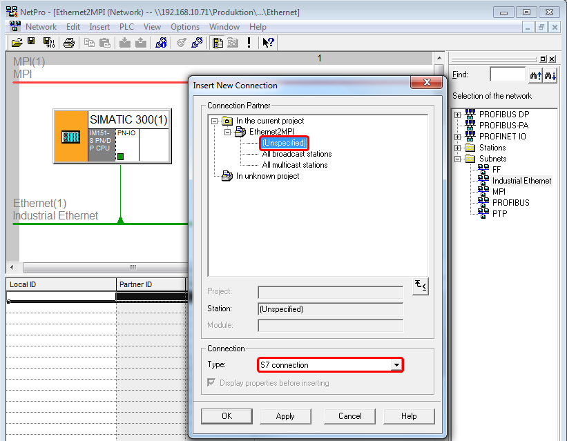
To access several CPUs accordingly, several S7 connections need to be configured. The connection ID is relevant for the call of the FBs/SFBs. If the amount of CPUs exceeds the amount of possible S7 connections, Ethernet to PROFIBUS via PROFIBUS CP (Multiplexing) can be chosen.
Within the properties of the S7 connection the IP address of the IBH Links must be entered:
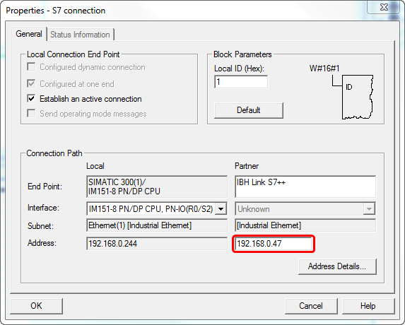
Within the Address Details enter the MPI address of the destination CPU.
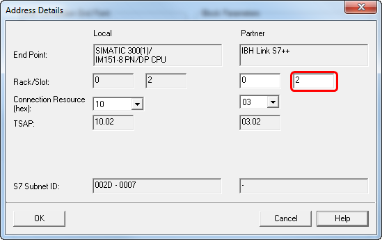
The communication will be established usings the blocks FB14/FB15. There are different FB14/FB15 available. Depending if a CPU with onboard Ethernet or a CPU with Ethernet CP is used, the correct set of blocks must be chosen, otherwise there will be no data exchange.
CPU with onboard Ethernet = Standard Library
CPU with Ethernet CP = SIMATIC_NET_CP
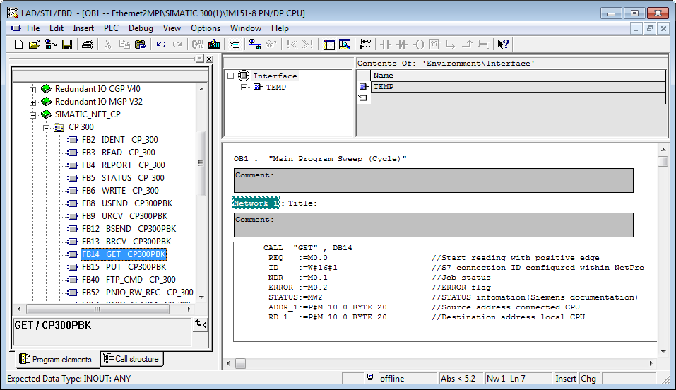
Sample:
     CALL  "GET" , DB14
      REQ   :=M0.0                     //Start reading with positive edge
      ID    :=W#16#1                   //S7 connection ID configured within NetPro
      NDR   :=M0.1                     //Job status
      ERROR :=M0.2                     //ERROR flag
      STATUS:=MW2                      //STATUS infomation(Siemens documentation)
      ADDR_1:=P#M 10.0 BYTE 20         //Source address connected CPU
      RD_1  :=P#M 10.0 BYTE 20         //Destination address local CPU
Depending on the type of CPU the correct set of blocks, FB14/15 or SFB14/15 must be chosen. The final step is to tranfer the S7 program and the system data to the CPU.
Ethernet to PROFIBUS via PROFIBUS CP (Multiplexing)
Requirements:
- SIMATIC Manager
- IBH Link S7++/IBH Link S7++ HS with Firmware >= 2.142
- CPU with PROFIBUS CP
- CPU with Ethernet onboard or Ethernet CP. The Interface must support S7 connections. It can be checked within the hardware
properties: S7 connection active (Server means passive).
Download: STEP®7 Sample: Ethernet to PROFIBUS via PROFIBUS-CP
Within NetPro the CPU must be connected with the Ethernet. An unspecified connection needs to be created:

Within the properties of the S7 connection the IP address of the IBH Links must be entered:

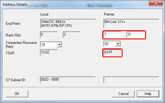
Within the address details as Rack and Slot a special ID for IBH Link Routing must be entered: Rack 7, Slot 31
Establish connection via FB/SFB 15 (PUT)
To establish a connection over a PROFIBUS-CP with an IBH Link S7++, more connection information is required, than NetPro permits to enter. For this reason the IBH Link S7++ can be set into the projected mode. That mode permits sending the required connection information with a call to the "PUT" block as a data structure. To set this mode, only a special ID must be entered in NetPro.
Create OB1:
Within the first network the SFB15 is called to handover the parameters. Within the second network the SFB15 for the data exchange is called.
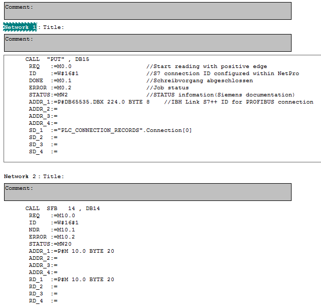
CALL "PUT" , DB15
      REQ   :=M0.0                     //Start reading with positive edge
      ID    :=W#16#1                   //S7 connection ID configured within NetPro
      DONE  :=M0.1                     //Job status
      ERROR :=M0.2                     //ERROR flag
      STATUS:=MW2                      //STATUS infomation(Siemens documentation)
      ADDR_1:=P#DB65535.DBX 224.0 BYTE 8    //IBH Link S7++ ID for PROFIBUS connection.
With this ID the IBH Link S7++ gets the needed information for the connenction.
      ADDR_2:=
      ADDR_3:=
      ADDR_4:=
      SD_1  :="PLC_CONNECTION_RECORDS".Connection[0]
      SD_2  :=
      SD_3  :=
      SD_4  :=
"PLC_CONNECTION_RECORDS" – Symbolic name of the DB, which contains the parameters for the connection. Connection[0] – Pointer to the start address within the DB, which contains the parameters for the connection. If the DB contains more than one connection, they can be selected via this parameter and access to several CPUs is possible.
CALL SFB 14 , DB14
      REQ   :=M10.0                    //Start reading with positive edge
      ID    :=W#16#1                   //S7 connection ID configured within NetPro
      NDR   :=M10.1                    //Job status
      ERROR :=M10.2                    //ERROR flag
      STATUS:=MW20                     //STATUS infomation(Siemens documentation)
      ADDR_1:=P#M 10.0 BYTE 20         //Source address connected CPU
      ADDR_2:=
      ADDR_3:=
      ADDR_4:=
      RD_1  :=P#M 10.0 BYTE 20         //Destination address local CPU
      RD_2  :=
      RD_3  :=
      RD_4  :=
Depending on the type of CPU the correct set of blocks, FB14/15 or SFB14/15 must be chosen.
A DB is needed, which contains the parameters for the connection.
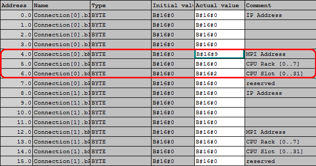
The parameters MPI address, Slot- and Rack No. are used. Entering an IP address is not needed using this kind of connection. If several connections are used, it is recommended to use UDTs.
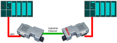
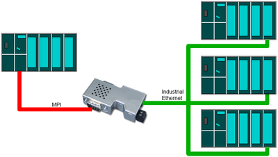
MPI – Ethernet – MPI without projected configuration / MPI – Ethernet/MPI – IBH Link S5++
Requirements
- SIMATIC Manager or S7 for Windows® from IBHsoftec
- 2 x IBH Link S7++/IBH Link S7++ HS with Firmware >= 2.142
- The operating system of the CPU must contain the blocks XPUT and XGET (SFC67, SFC68).
The information, whether the CPU contains these blocks can be gathered from the Siemens CPU documentation.
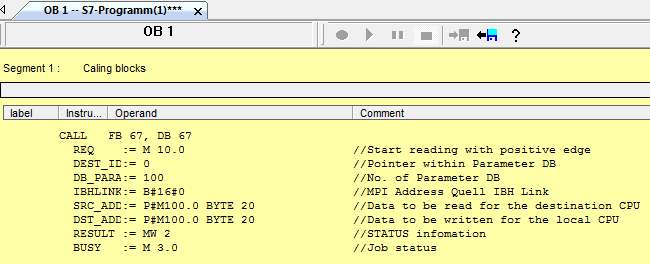
For this type of connection, a projected configuration with NetPro is not necessary. Within the PLC program, the blocks XPUT/XGET are called to establish a connection from one IBH Link S7 to the next IBH Link. For very comfortable configuration of the communication parameters, the blocks XPUT_IBH and XGET_IBH (developed by IBHsoftec) are available and can be found within the sample.
Download: STEP®7 Sample: MPI – Ethernet – MPI without projected configuration
CALL FB 67 , DB67
      REQ         :=M10.0              //Start reading with positive edge
      DEST_ID     :=0                  //Pointer within parameter DB
      DB_PARA     :=100                //No. of parameter DB
      IBHLINK_ADDR:=B#16#0             //MPI Address source IBH Link
      SRC_ADDR    :=P#M 100.0 BYTE 20  //Location of data in the destination CPU
      DST_ADDR    :=P#M 100.0 BYTE 20  //Location of data in the local CPU
      RESULT      :=MW2                //STATUS infomation
      BUSY        :=M3.0               //Job status
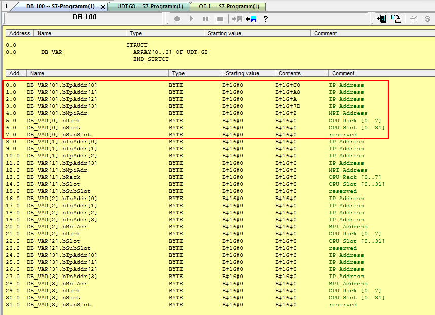
The information for the IBH Link on how to reach the destination CPU are stored within the parameter DB.
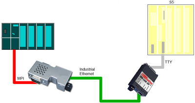
Rack and Slot No are 0 when using MPI. The parameters for S5 conenctions using the IBH Link S5++ are:
| Destination IP address | IP address of the IBHLink S5++ |
| Destination MPI address | 2 |
| Destination Rack | 0 |
| Destination Slot | 0 |
MPI – Ethernet – MPI with S7 conection (projected) / MPI – Ethernet / MPI – IBH Link S5++
Requirements
- SIMATIC Manager
- 2 x IBH Link S7++/IBH Link S7++ HS with Firmware >= 2.142
- CPU with MPI Interface
- Interface has to support S7 connections
Download: STEP®7 sample: MPI – Ethernet – MPI with S7 connection (projectet)
Within NetPro the CPU must be connected with the Ethernet. An unspecified connection needs to be created:
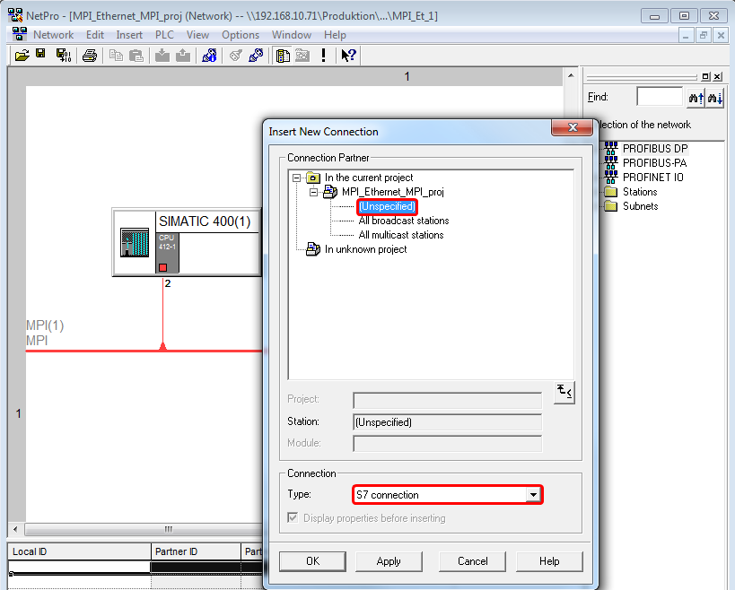
Within the properties of the S7 connection the IP address of the IBH Links must be entered:
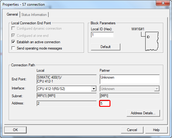
Establish connection via FB/SFB 15 (PUT)
To establish a connection with an IBH Link S7++, more connection information is required, than NetPro permits to enter. For this reason the IBH Link S7++ can be set into the projected mode. That mode permits sending the required connection information with a call to the "PUT" block as a data structure. Another reason to use this connection is, if data needs to be exchanged with several CPU.
Create OB1:
Within the first network the SFB15 is called to handover the parameters. Within the second network the SFB15 for the data exchange is called.

CALL "PUT" , DB15
      REQ   :=M0.0                     //Start reading with positive edge
      ID    :=W#16#1                   //S7 connection ID configured within NetPro
      DONE  :=M0.1                     //Job status
      ERROR :=M0.2                     //ERROR flag
      STATUS:=MW2                      //STATUS infomation(Siemens documentation)
      ADDR_1:=P#DB65535.DBX 224.0 BYTE 8    //IBH Link S7++ ID for PROFIBUS connection.
With this ID the IBH Link S7++ gets the needed information for the connenction.
      ADDR_2:=
      ADDR_3:=
      ADDR_4:=
      SD_1  :="PLC_CONNECTION_RECORDS".Connection[0]
      SD_2  :=
      SD_3  :=
      SD_4  :=
"PLC_CONNECTION_RECORDS" – Symbolic name of the DB, which contains the parameters for the connection. Connection[0] – Pointer to the start address within the DB, which contains the parameters for the connection. If the DB contains more than one connection, they can be selected via this parameter and access to several CPUs is possible.
CALL SFB 14 , DB14
      REQ   :=M10.0                    //Start reading with positive edge
      ID    :=W#16#1                   //S7 connection ID configured within NetPro
      NDR   :=M10.1                    //Job status
      ERROR :=M10.2                    //ERROR flag
      STATUS:=MW20                     //STATUS infomation(Siemens documentation)
      ADDR_1:=P#M 10.0 BYTE 20         //Source address connected CPU
      ADDR_2:=
      ADDR_3:=
      ADDR_4:=
      RD_1  :=P#M 10.0 BYTE 20         //Destination address local CPU
      RD_2  :=
      RD_3  :=
      RD_4  :=
Depending on the type of CPU the correct set of blocks, FB14/15 or SFB14/15 must be chosen.
A DB is needed, which contains the parameters for the connection.
The parameters MPI address, Slot- and Rack No. are used. Entering an IP address is not needed using this kind of connection. If several connections are used, it is recommended to use UDTs.
The parameters for S5 conenctions using the IBH Link S5++ are:
| Destination IP address | IP address of the IBHLink S5++ |
| Destination MPI address | 2 |
| Destination Rack | 0 |
| Destination Slot | 0 |
Connection via IBH Link in routing mode
Requirements
- SIMATIC Manager
- IBH Link S7++/IBH Link S7++ HS with Firmware >= 2.142
- CPU with MPI Interface
- Interface has to support S7 connections
Download: STEP®7 Smaple: Cennction via IBH Link in routing mode
This kind of connection offers the possibility to exchange a large amount of data very fast - up to 64K. For the communication the standard blocks FB/SFB 8/9 (USEND / URCV) and FB/SFB 12/13 (BSEND / BRCV)are used.
Within the IBH net settings the routing mode msut be activated. This mode is available beginning with firmware version 2.142. With projected connections via RFC1006 it is not possible any more to communicate over unprojected connections. The IBHNet communication via the IBHNet driver is not influenced from this setting.
The IBHLink S7++ will be configured as a station within NetPro.
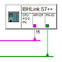
The following station must be selected:
MLFB: 6ES7 412-2EK06-0AB0 V6.0 Rack 0, Slot 2
MPI/PROFIBUS address of the IBHLink S7++
IP Address of the IBHLink S7++
Configuration of the Station within Hardwarekonfigurator:
File:IBH Link als Station HWK.png
Within NetPro all corresponding CPUs besides the IBH Link station needs to be configured. The S7 connection will be established the real existing CPU via Ethernet to the IBH Link Station. In this case the real existing CPU is the active participant.
File:Verbindung1.png
Die Partner-Verbindungsresource wird automatisch vergeben and is relvant fo the next step.
Die IBH Link Station baut nun eine S7-Verbindung über Profibus zur zweiten tatsächlichen CPU auf. Hierbei ist die IBH Link Station der aktive Teilnehmer. As local Verbindungs-ID wird hier nun die im vorherigen Schritt automatisch zugewiesene Verbindungsresource (im Beispiel: 10) angegeben.
The status can be displayed within NetPro:
Datei:Verbindungsstatus aktivieren.png
This type of connection allows ocmplex networking:
For the connection to an IBH Link S5++ no dummy CPU needs to be cnfigured within NetPro. It es neough to create an , unspecified S7 connection Ethernet. In this case the partner IP address is the IP address of the IBH Link S5++. For communication the blocks PUT/GET are chosen- SFB14/15.
Datei:VerbindungS5px800.png

