Difference between revisions of "IBH Link UA:Integrated S7 SoftPLC"
(→Cyclic Read and Write) |
|||
| Line 182: | Line 182: | ||
|- | |- | ||
| − | | STATUS || OUTPUT || WORD || E, A, M, D, L || | + | | STATUS || OUTPUT || WORD || E, A, M, D, L || 0x0000 on success, 0x8090 on error. |
|- | |- | ||
| Line 265: | Line 265: | ||
The PLC Variable '''OutputVal''' will be written cyclically into the OPC Variable '''S7-1500.S7-1500.GlobalVars.InputVal'''.<br/>The sampling rate is 16#00c8 or 200 milliseconds.<br/>The OPC Status is written in the same cycle as '''Output Val ''' into the variable '''# Status_1 ''' and the time stamp of the cycle into the variable ''' # timestamp_1 '''.<br/>Now the configuration block must be called within OB100. | The PLC Variable '''OutputVal''' will be written cyclically into the OPC Variable '''S7-1500.S7-1500.GlobalVars.InputVal'''.<br/>The sampling rate is 16#00c8 or 200 milliseconds.<br/>The OPC Status is written in the same cycle as '''Output Val ''' into the variable '''# Status_1 ''' and the time stamp of the cycle into the variable ''' # timestamp_1 '''.<br/>Now the configuration block must be called within OB100. | ||
| − | |||
| − | |||
==== Server Bridge ==== | ==== Server Bridge ==== | ||
Revision as of 16:25, 20 September 2016
Contents
- 1 Introduction
- 2 Commissioning
- 3 SoftPLC Status and Settings
- 4 Server Function
- 5 Client Function
- 6 Instruction set
- 6.1 Bit logic instructions
- 6.2 Other boolean logic instructions
- 6.3 Master Control Relay
- 6.4 Load / Transfer instructions
- 6.5 Peripheral access instructions
- 6.6 Accumulator instructions
- 6.7 Shift and rotating instructions
- 6.8 Timer instructions
- 6.9 Counter instructions
- 6.10 Word instructions
- 6.11 Arithmetic instructions
- 6.12 Data type conversion instructions
- 6.13 Jump instructions
- 6.14 Block call instructions
- 6.15 Indirect addressing instructions
- 6.16 Program display and null operation instructions
- 7 Integrated organisation blocks
- 8 Integrated system functions
- 9 Integrated system blocks
- 10 Technical Data
Introduction
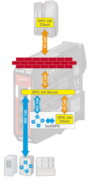
The IBH Link UA additional contains a SoftPLC. The SoftPLC is able to read and write variables from the OPC UA server.
The integrated SoftPLC can be used for data preprocessing and supports the programming languages LAD, FBD, STL, SCL or S7-GRAPH.
Commissioning
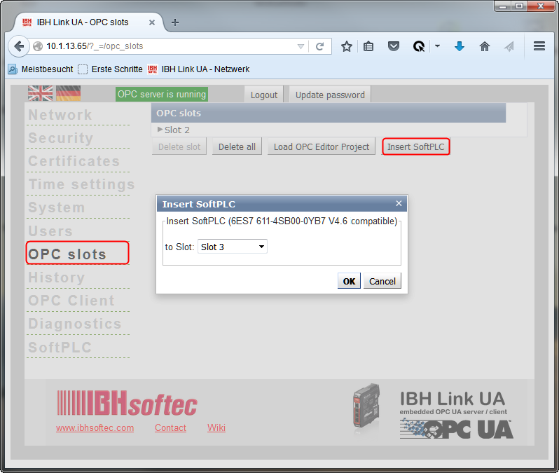
Activate the integrated SoftPLC
First, the SoftPLC needs to be activated using the web interface:
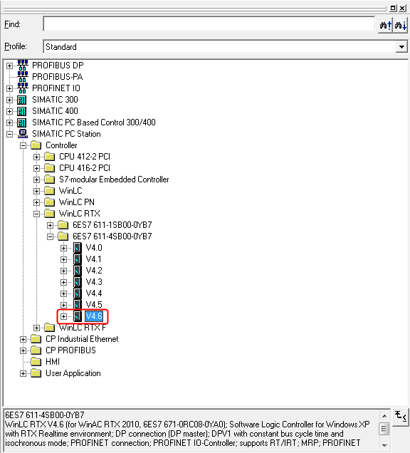
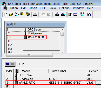
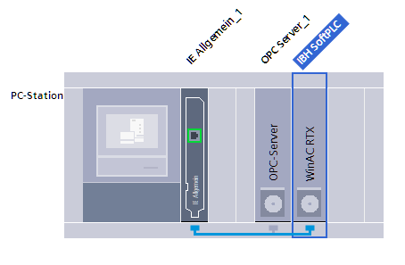
Define SoftPLC within PLC project
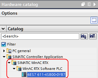
Therefore on the defined slot of the PC station a SoftPLC must be added.
SIMATIC Manager:
TIA Portal:
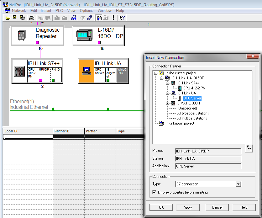
A S7 connection between the SoftPLC and the OPC UA Server must be established:
SIMATIC Manager:
TIA:
The SoftPLC supports the programming languages LAD, FBD, STL, SCL or S7-GRAPH.
SoftPLC Status and Settings
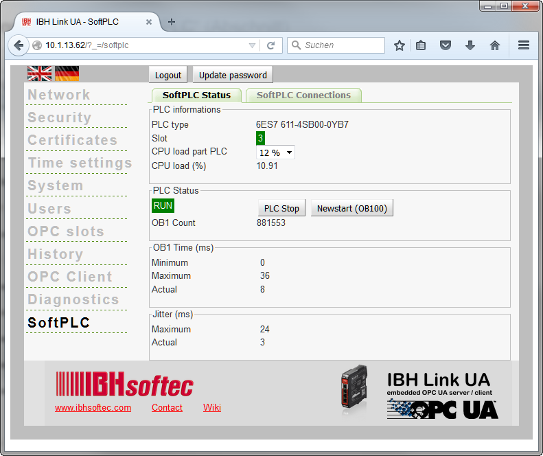
The SoftPLC Status can be monitored on the web interface:
The performance of the SoftPLC can be adjusted:
| CPU Share PLC | processing time (1000 mixed instructions) |
|---|---|
| 50% | apx. 360 µs |
| 33% | apx. 550 µs |
| 25% | apx. 720 µs |
| 20% | apx. 900 µs |
| 12% | apx. 1800 µs |
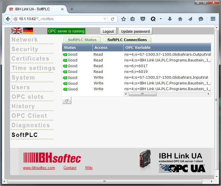
Furthermore, the status of the SoftPLC Connections is available.:
Server Function
A S7 connection between the SoftPLC and the OPC UA Server must be established::
SIMATIC Manager:
TIA:
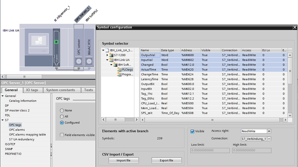
Within the properties of the OPC Server at <General> <S7> <OPC tags> the OPC Tags can be selected:
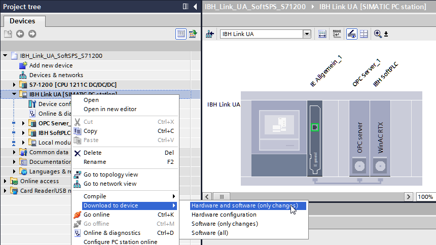
Now the configuration needs to be downloaded to the IBH Link UA:
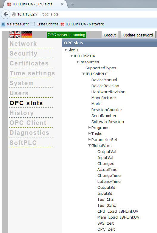
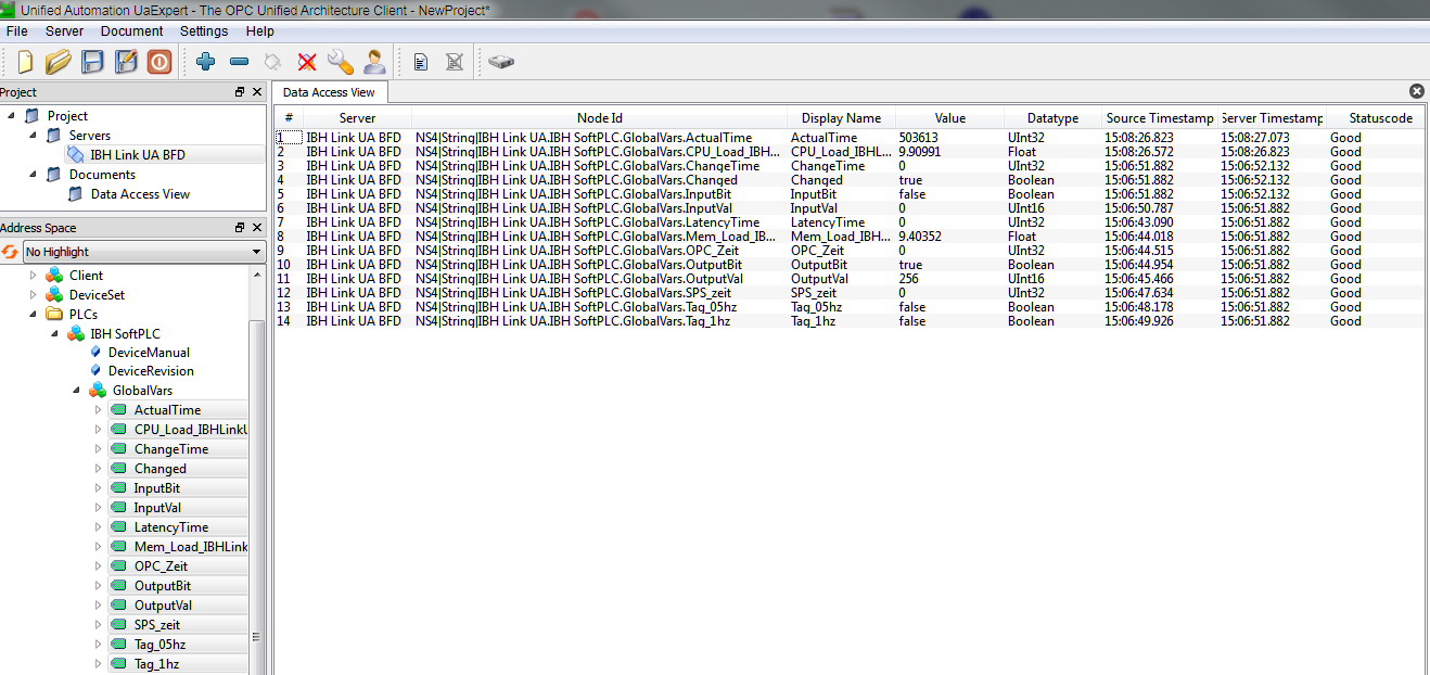
The configuration is now completed and the tags from the SoftPLC within the IBH Link UA are available :
Client Function
Cyclic Read and Write
The SoftPLC is able to read and write the OPC variables cyclically.
The configuration will be done within the SFB 8 (USEND) and called during the warm start (OB100).
| Parameter | Declaration | Data type | Storage area | description |
|---|---|---|---|---|
| REQ | INPUT | BOOL | E, A, M, D, L | Not evaluated |
| ID | INPUT | WORD | M, D, Const. | Fixed value: 65400 |
| R_ID | INPUT | DWORD | E, A, M, D, L, Const. | Mode Low Word: 0: Read(Variable as XML String) 1: Write(Variable as XML String) 2: Read(PLC Variable) 3: Write(PLC Variable) 4: Read(Special Variable) 5: Write(Special Variable) 6: Read(Server Variable) 7: Write(Server Variable) High Word: Sampling in milliseconds |
| DONE | OUTPUT | BOOL | E, A, M, D, L | is not set |
| ERROR | OUTPUT | BOOL | E, A, M, D, L | ERROR=0: The parameters were passed correctly ERROR=1: The parameters were passed not correctly |
| STATUS | OUTPUT | WORD | E, A, M, D, L | 0x0000 on success, 0x8090 on error. |
| SD_1 | IN_OUT | ANY | D | Pointer to the OPC Variable. |
| SD_2 | IN_OUT | ANY | E, A, M, D | Pointer to the OPC Variable for the value of the OPC Variable. Allowed is Data Type BOOL, BYTE, CHAR, WORD, INT, DWORD, DINT, REAL, DATE, DATE_AND_TIME. Note: |
| SD_3 | IN_OUT | ANY | E, A, M, D | Pointer to the PLC Variable for the status of the Variable. Allowed is Data Type DWORD Note: If the ANY pointer points to a DB, the DB must always be specified (f.i.: P# DB10.DBX5.0 Byte 10). |
| SD_4 | IN_OUT | ANY | D | Pointer to the PLC Variable for the Time Stamp. Allowed is Data Type DATE_AND_TIME. Note: If the ANY pointer points to a DB, the DB must always be specified (f.i.: P# DB10.DBX5.0 Byte 10). |
The OPC Variables are defined as follows:
- Mode 0 and 1: ´ns=<Namespace>;s=<Identifier>´
- or: ns=<Namespace>;i=<Numeric Identifier>´
- All OPC Variables can be read using this mode. The IBH Link UA knows the following Namespaces
Namespace Area 0 General OPC Server Variables 1, 2, 3, 5 No evaluable variables 4 All PLC specific OPC variables 6 IBH Link UA Special Variables
- Mode 2 and 3: ´<Identifier>´
- The identifier is formed as follows:
<Station name>.<PLC Name>.<GlobalVars>.<Variable name from Variables table>
or:
<Station name>.<PLC Name>.<Programs>..<Variable name>
- The identifier is formed as follows:
- Mode 4 and 5: <Numeric Identifier>
- Number of the Special Variable from Namespace 6.
- Modus 6 and 7: <Numeric Identifier>
- Number of the Server Variable from Namespace 0.
- Number of the Server Variable from Namespace 0.
Sample TIA Portal
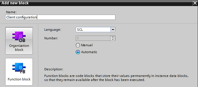
Create a function block for the client configuration:
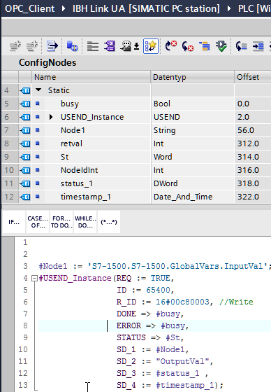
The PLC Variable OutputVal will be written cyclically into the OPC Variable S7-1500.S7-1500.GlobalVars.InputVal.
The sampling rate is 16#00c8 or 200 milliseconds.
The OPC Status is written in the same cycle as Output Val into the variable # Status_1 and the time stamp of the cycle into the variable # timestamp_1 .
Now the configuration block must be called within OB100.
Server Bridge
The basic procedure is described at IBH Link UA Client Functions.
The server, between which a communication should be established, need to be defined.
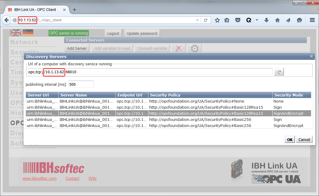
First, the own server URL of the IBH Link UA is specified:
Furthermore, the desired security level can be chosen.
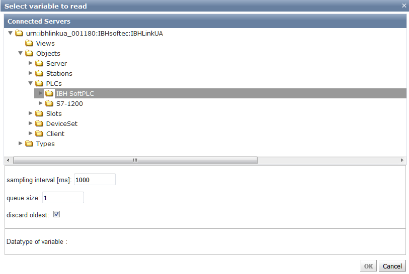
Now the variables of the SoftPLC can be selected for reading:
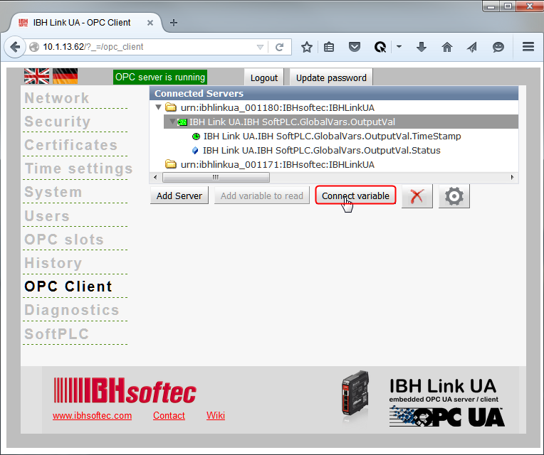
and can be connected to a variable of another OPC UA Server:
Instruction set
Bit logic instructions
| Instruction | Operand | Description |
|---|---|---|
| A | AND with a scan to "1"“ | |
| AN | AND with a scan to "0" | |
| O | OR with scan to "1" | |
| ON | OR with scan to "0" | |
| X | Exclusive-OR with a scan to "1" | |
| XN | Exclusive-OR with a scan to "0" | |
| I | of an input | |
| Q | of an output | |
| M | of a memory | |
| L | of a local data bit | |
| T | of a timer | |
| C | of a counter | |
| DBX | of a data bit | |
| DIX | of an instant data bit | |
| ==0 | result equal zero | |
| <>0 | result unequal zero | |
| >0 | result greater than zero | |
| >=0 | result greater or equal zero | |
| <0 | result less than zero | |
| <=0 | result less or equal zero | |
| UO | invalid result | |
| OV | overflow | |
| OS | overflow (saving) | |
| BR | binary result |
Other boolean logic instructions
| Operation | Operand | Description |
|---|---|---|
| A( | AND left parenthesis | |
| AN( | AND NOT left parenthesis | |
| O( | OR left parenthesis | |
| ON( | OR NOT left parenthesis | |
| X( | Exclusive OR left parenthesis | |
| XN( | Exclusive OR NOT left parenthesis | |
| ) | Right parenthesis | |
| O | OR-ing AND operations | |
| NOT | Negate RLO | |
| SET | Set RLO to "1" | |
| CLR | Set RLO to "0" | |
| SAVE | Save RLO to the BR bit |
| Operation | Operand | Description |
|---|---|---|
| = | Assign value of RLO | |
| S | Set | |
| R | Reset | |
| FP | Positive edge detection | |
| FN | Negative edge detection | |
| I | of an input bit | |
| Q | of an output bit | |
| M | of a memory bit | |
| L | of a local data bit | |
| DBX | of a data bit | |
| DIX | of a instance data bit |
Master Control Relay
| Operation | Operand | Description |
|---|---|---|
| MCRA | Activate MCR | |
| MCRD | Deactivate MCR | |
| MCR( | Open MCR zone | |
| )MCR | Close MCR zone |
Load / Transfer instructions
| Operation | Operand | Description |
|---|---|---|
| L | Load operand | |
| T | Transfer operand | |
| IB | Input byte | |
| IW | Input word | |
| ID | Input double word | |
| QB | Output byte | |
| QW | Output word | |
| QD | Output double word | |
| MB | Memory byte | |
| MW | Memory word | |
| MD | Memory double word | |
| LB | Local data byte | |
| LW | Local data word | |
| LD | Local data double word | |
| DBB | Data block byte | |
| DBW | Data block word | |
| DBD | Data block double word | |
| DIB | Instance data block byte | |
| DIW | Instance data block word | |
| DID | Instance data block double word | |
| STW | Status word | |
| L | const | Load constant value |
| L | #Pointer | Load pointer |
| L | T | Timer |
| LC | T | Timer (BCD coded) |
| L | Z | Counter |
| LC | Z | Counter (BCD coded) |
| L | DBNO | Data block number |
| L | DBLG | Data block length |
| L | DINO | Instance data block number |
| L | DILG | Instance data block length |
Peripheral access instructions
Peripheral access is not possible with the integrated SoftPLC.
Accumulator instructions
| Operation | Operand | Description |
|---|---|---|
| PUSH | Push accumulators upwards | |
| POP | Push accumulators downwards | |
| ENT | Push accumulators (without A1) A2->A3, A3->A4 | |
| LEAVE | Push accumulators (without A1) A4->A3, A3->A2 | |
| TAK | Change ACCU1 with ACCU2 | |
| CAW | Change ACCU1 bytes 0 and 1 | |
| CAD | Change ACCU1 bytes 0 and 3, 1 and 2 |
Shift and rotating instructions
| Operation | Operand | Description |
|---|---|---|
| SLW | Shift ACCU1-L left (word shift) | |
| SLD | Shift ACCU1 left (double word shift) | |
| SRW | Shift ACCU1-L right (word shift) | |
| SRD | Shift ACCU1 right (double word shift) | |
| SSI | Shift ACCU1-L right (word shift with sign) | |
| SSD | Shift ACCU1 right (double word shift with sign) | |
| RLD | Rotate ACCU1 left (double word) | |
| RLDA | Rotate ACCU1 left through CC1 | |
| RRDA | Rotate ACCU1 right through CC1 | |
| RRD | Rotate ACCU1 right (double word) | |
| const | Number of places to shift/rotate | |
| - | Number of places to shift/rotate located in ACCU2 |
Timer instructions
| Operation | Operand | Description |
|---|---|---|
| SP | T | Start as impulse |
| SE | T | Start as extended impulse |
| SD | T | Start as ON-delay |
| SS | T | Start as saving ON-delay |
| SF | T | Start as OFF-delay |
| R | T | Reset timer |
| FR | T | Enable timer |
Counter instructions
| Operation | Operand | Description |
|---|---|---|
| CU | C | Count up (increment) |
| CD | C | Count down (decrement) |
| S | C | Set counter |
| R | C | Reset counter |
| FR | C | Enable counter |
Word instructions
| Operation | Operand | Description |
|---|---|---|
| AW | AND ACCU1-L (AND word) | |
| AD | AND ACCU1 (AND double word) | |
| OW | OR ACCU1-L (OR word) | |
| OD | OR ACCU1 (OR double word) | |
| XOW | Exclusive-OR ACCU (XOR word) | |
| XOD | Exclusive-OR ACCU (XOR double word) | |
| const | with a word or double word constant | |
| - | with ACCU2 |
Arithmetic instructions
| Operation | Operand | Description |
|---|---|---|
| ==I | Integer values equal | |
| <>I | Integer values unequal | |
| >I | Integer values greater | |
| >=I | Integer values greater or equal | |
| <I | Integer values less | |
| <=I | Integer values less or equal | |
| ==D | Double integer values equal | |
| <>D | Double integer values unequal | |
| >D | Double integer values greater | |
| >=D | Double integer values greater or equal | |
| <D | Double integer values less | |
| <=D | Double integer values less or equal | |
| ==R | Real values equal | |
| <>R | Real values unequal | |
| >R | Real values greater | |
| >=R | Real values greater or equal | |
| <R | Real values less | |
| <=R | Real values less or equal | |
| SIN | Sine of a real value | |
| COS | Cosine of a real value | |
| TAN | Tangent of a real value | |
| ASIN | Arcsine of a real value | |
| ACOS | Arccosine of a real value | |
| ATAN | Arctangent of a real value | |
| SQR | Square a real value | |
| SQRT | Square root a real value | |
| EXP | e to the power of a real value | |
| LN | Natural logarithm of a real value | |
| +I | Integer addition | |
| -I | Integer subtraction | |
| *I | Integer multiplication | |
| /I | Integer division | |
| +D | Double-integer addition | |
| -D | Double-integer subtraction | |
| *D | Double-integer multiplication | |
| /D | Double-integer division | |
| +R | Real addition | |
| -R | Real subtraction | |
| *R | Real multiplication | |
| /R | Real division | |
| MOD | Double integer division (modulo) | |
| + | const | Add a constant |
| +P# | const | Add a pointer |
| DEC | decrement ACCU1-LL (one byte) | |
| INC | increment ACCU1-LL (one byte) |
Data type conversion instructions
| Operation | Operand | Description |
|---|---|---|
| ITD | Convert integer to double integer | |
| ITB | Convert integer to BCD | |
| DTB | Convert double integer to BCD | |
| DTR | Convert double integer to real | |
| BTI | Convert BCD to integer | |
| BTD | Convert BCD to double integer | |
| RND | Convert real to double integer (round) | |
| RND+ | Convert real to double integer (round up) | |
| RND- | Convert real to double integer (round down) | |
| TRUNC | Convert real to double integer (truncate) | |
| INVI | Invert ACCU1-L (integer) | |
| INVD | Invert ACCU1 (double integer) | |
| NEGI | Negate ACCU1-L (integer) | |
| NEGD | Negate ACCU1 (double integer) | |
| NEGR | Negate ACCU1 (real) | |
| ABS | Absolute value (real) |
Jump instructions
| Operation | Operand | Description |
|---|---|---|
| JU | goal | Jump unconditional |
| JC | goal | Jump if RLO = 1 |
| JCB | goal | Jump if RLO = 1 (save RLO) |
| JCN | goal | Jump if RLO = 0 |
| JNB | goal | Jump if RLO = 0 (save RLO) |
| JBI | goal | Jump if BR = 1 |
| JNBI | goal | Jump if BR = 0 |
| JZ | goal | Jump if compare result = 0 |
| JN | goal | Jump if compare result != 0 |
| JP | goal | Jump if compare result > 0 |
| JPZ | goal | Jump if compare result >= 0 |
| JM | goal | Jump if compare result < 0 |
| JMZ | goal | Jump if compare result <= 0 |
| JUO | goal | Jump if compare result "Unordered Math Instruction" |
| JO | goal | Jump on overflow |
| JOS | goal | Jump on saving overflow |
| JL | goal | Jump distributor |
| LOOP | goal | Loop programming (decrement ACCU1-L and jump if != 0 |
Block call instructions
| Operation | Operand | Description |
|---|---|---|
| CALL FB | Unconditional call of an FB with parameter transfer | |
| CALL FC | Unconditional call of an FC with parameter transfer | |
| CALL SFB | Unconditional call of an SFB with parameter transfer | |
| CALL SFC | Unconditional call of an SFC with parameter transfer | |
| UC FB | Unconditional call of an FB without parameter transfer | |
| CC FB | Conditional call of an FB without parameter transfer | |
| UC FC | Unconditional call of an FC without parameter transfer | |
| CC FC | Conditional call of an FC without parameter transfer | |
| BEU | End block unconditionally | |
| BEC | End block conditionally (RLO = 1) | |
| BE | End block | |
| OPN | ||
| DB | Open data block | |
| DI | Open instance data block | |
| TDB | Exchange data block registers |
Indirect addressing instructions
| Operation | Operand | Description |
|---|---|---|
| LAR1/LAR2 | Load AR1/AR2 | |
| MD | with memory double word | |
| LD | with local data double word | |
| DBD | with data block double word | |
| DID | with instance data block double word | |
| LAR1 | - | Load AR1 with ACCU1 |
| LAR2 | - | Load AR2 with ACCU1 |
| LAR1 | AR2 | Load AR1 with AR2 |
| LAR1 | P# | Load AR1 with pointer |
| LAR2 | P# | Load AR2 with pointer |
| TAR1/TAR2 | Transfer in AR1/AR2 | |
| MD | in memory double word | |
| LD | in local data double word | |
| DBD | in data block double word | |
| DID | in instance data block double word | |
| TAR1 | - | Transfer AR1 in ACCU1 |
| TAR2 | - | Transfer AR2 in ACCU1 |
| TAR1 | AR2 | Transfer AR1 in AR2 |
| TAR | Swap AR1 with AR2 | |
| +AR1 | Add ACCU1 to AR1 | |
| +AR2 | Add ACCU1 to AR2 | |
| +AR1 | P# | Add pointer to AR1 |
| +AR2 | P# | Add pointer to AR2 |
Program display and null operation instructions
| Operation | Operand | Description |
|---|---|---|
| NOP | 0 | Null operation instruction |
| NOP | 1 | Null operation instruction |
| BLD | const | Program display instruction (null operation) |
Integrated organisation blocks
The organisation blocks, listed in the chart below, are executed, if they are programmed:
| OB no | Short Description |
|---|---|
| OB 1 | Main program |
| OB 10 – OB 17 | Time alarm |
| OB 20 – OB 23 | Delay alarm |
| OB 30 – OB 38 | Time blocks (cyclic call) |
| OB 80 – OB 87 | Error blocks |
| OB 90 | Background execution |
| OB 100/OB 101 | Warm or hot restart |
| OB 121/OB 122 | Programming faults |
Integrated system functions
All system functions (SFC) relevant for a Software PLC are integrated in S7-SoftPLC.
The chart below shows the available SFCs(in numeric listing)
| SFC no | SF name | Short Description |
|---|---|---|
| SFC 0 | SET_CLK | Set system clock |
| SFC 1 | READ_CLK | Read system clock |
| SFC 6 | RD_SINFO | Read start information of actual OB |
| SFC 20 | BLKMOV | Copy PLC-variable in target-area |
| SFC 21 | FILL | Preoccupy PLC-variable in target-area |
| SFC 22 | CREAT_DB | Create data block |
| SFC 23 | DEL_DB | Delete data block |
| SFC 24 | TEST_DB | Test attributes of a data block |
| SFC 25 | COMPRESS | Compress load memory |
| SFC 28 | SET_TINT | Set time alarm |
| SFC 29 | CAN_TINT | Stop time alarm (do not execute) |
| SFC 30 | ACT_TINT | Enable time alarm |
| SFC 31 | QRY_TINT | Status of time alarm |
| SFC 32 | SRT_DINT | Start delay alarm |
| SFC 33 | CAN_DINT | Stop delay alarm |
| SFC 34 | QRY_DINT | Status query of delay alarm |
| SFC 36 | MSK_FLT | Mask a synchron error occurrence |
| SFC 37 | DMSK_FLT | Demask a synchron error occurrence |
| SFC 38 | READ_ERR | Read out the occurrence status register |
| SFC 39 | DIS_IRT | Locking the asynchron and alarm error processing |
| SFC 40 | EN_IRT | Enable the asynchron and alarm error processing |
| SFC 41 | DIS_AIRT | Delay high-priority asynchron and alarm error processing |
| SFC 42 | EN_AIRT | Enable high-priority asynchron and alarm error processing |
| SFC 43 | RE_TRIGR | Retrigger the Watchdog |
| SFC 46 | STP | CPU operating state STOP |
| SFC 51 | RDSYST | Read out system status list (SSL) |
| SFC 64 | TIME_TCK | Timer Tick |
| SFC 81 | UBLKMOV | Block Move, that can not be stopped |
Integrated system blocks
The system blocks (SFB) relevant for a software PLC are integrated in S7-SoftPLC.
The following system function blocks are supported:
| SFB no | SFB name | Short Description |
|---|---|---|
| SFB 0 | CTU | Count up |
| SFB 1 | CTD | Count down |
| SFB 2 | CTUD | Count up and down |
| SFB 3 | TP | Generate pulse |
| SFB 4 | TON | Generate ON-delay |
| SFB 5 | TOF | Generate OFF-delay |
| SFB 8 | USEND | OPC UA Client Configuration |
| SFB 32 | DRUM | Implement sequencer |
Technical Data
| Load memory | 5 MB |
| Main memory | > 100 MB |
| Blocks | 16.384 |
| Flags (Bit) | 131.072 |
| Timer | 2048 |
| Counter | 2048 |
| Digital I/O | 32.768 Bit |
| processing times 1) | |
| CPU Chare PLC 50% | apx. 360 µs |
| CPU Chare PLC 33% | apx. 550 µs |
| CPU Chare PLC 25% | apx. 720 µs |
| CPU Chare SPS 20% | apx. 900 µs |
| CPU Chare SPS 12% | apx. 1800 µs |
1) 1024 mixed instructions (50% Binär, 50% Digital)
